

In this chapter, we will study the effects of Electric current :
- Hans Christian Oersted (1777-1851)
Oersted showed that electricity and magnetism are related to each other. His research later used in radio, television etc. The unit of magnetic field strength is name Oersted in his honor.
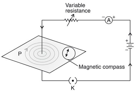
- Oersted Experiment
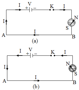
On passing the current through the copper wire XY in the circuit, the compass needle which is placed near the conductor gets deflected. If we reverse the direction of current, the compass needle deflects in reverse direction. If we stop the flow of current, the needle comes at rest.
Join Our Offline Classes at OSF Education.
Read more Science Solution of Class 10.
Hence, it concludes that electricity and magnetism are linked to each other. It shows that whenever the current will flow through the conductor, then magnetic field will develop around it.
- Magnetic Field – It is the region surrounding a magnet, in which force of magnet can be detected. It is a vector quantity, having both direction & magnitude.
- Compass needle – It is a small bar magnet, whose north end is pointing towards north pole and south end is pointing towards south pole of earth
- Magnetic field lines – When a bar magnet is placed on a cardboard and iron fillings are sprinkled, they will arrange themselves in a pattern as shown below.
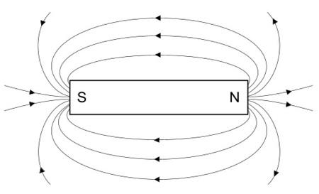
- The lines along which the iron filling align themselves represent magnetic field lines.
- Hence, magnetic field line is a path along which a hypothetical free north pole tends to move towards south pole.
- Characteristics of Magnetic field lines:
- The direction of magnetic field lines outside the magnet is always from North Pole to South Pole of bar magnet and are indicated by an arrow.
Inside the magnetic, the direction of field lines is from its south pole to North Pole
Thus, magnetic field lines are closed curve
- The strength of magnetic field is expressed by the closeness of magnetic field lines. Closer the lines, more will be the strength and farther the lines, less will be the magnetic field strength.
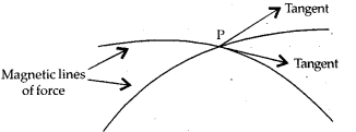
- No two field lines will intersect each other.
If they intersect, then at point of intersection the compass needle will show two direction of magnetic field which is not possible.
- Magnetic field due to Current Carrying Conductor
The above electric circuit in which a copper is placed parallel to a compass needle, shows the deflection in needle gets reversed, when the direction of current reversed. Hence electricity and magnetism are related to each other.
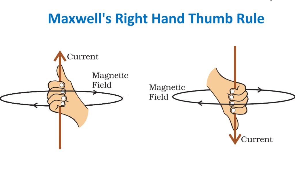
- Right Hand Thumb Rule:-
It is a convenient way of finding the direction of magnetic field associated with current carrying conductor.
Hold the straight were carrying current in your right hand such that thumb points towards the direction of current, then your folded fingers around the conductor will show the direction of magnetic field.
- Magnetic Field due to Current through a Straight Conductor
10.Magnetic Field due to Current through a circular Loop
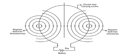
Every point on the wire carrying current give rise to the magnetic field, appearing as a straight line at the centre of loop. By applying Right hand Thumb rule, we can find the direction of magnetic field at every section of the wire.
- Solenoid-A Coil of many circular turns of insulated copper wire wrapped closely in the shape of a cylinder is called solenoid.
- Magnetic field due to a current in a solenoid
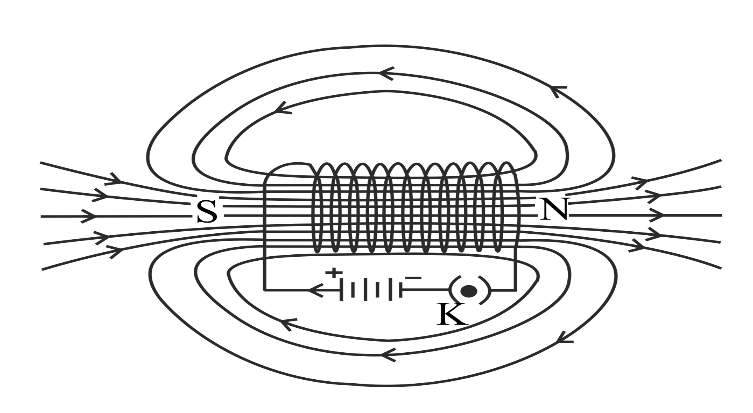
Using R.H. Thumb Rule, we can draw the pattern of magnetic field lives around a current carrying solenoid.
One end of the solenoid behaves as a magnetic north pole, white the other end behaves as the South Pole.
The filed lines inside the solenoid are in form of parallel straight lines, that implies that magnetic field inside the solenoid is same at all points i.e. Field is uniform.
- Electromagnet- Strong magnetic field inside the solenoid can be used to magnetize a magnetic material for example soft iron, when it is placed inside the coil. The magnet so formed is called electromagnet
- Force on a current carrying conductor in a magnetic field.
Andre Marie Ampere (1775-1836) suggested that the magnet also exert an equal and opposite force on the current carrying conductor
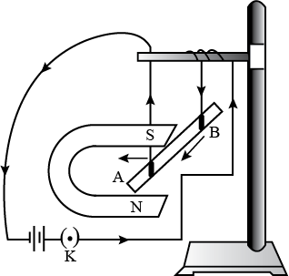
We will observe that the rod will displace i.e. the rod will experience a force, when it is placed in magnetic field, in a perpendicular direction to its length.
The direction of the exert force will be reversed if the direction of current through the conductor is reversed.
If we change the direction of field by inter changing the two poles of the magnet, again the direction of exert force will change.
Therefore, the direction of exerted force depends on
- direction of current
- direction of magnetic field lines
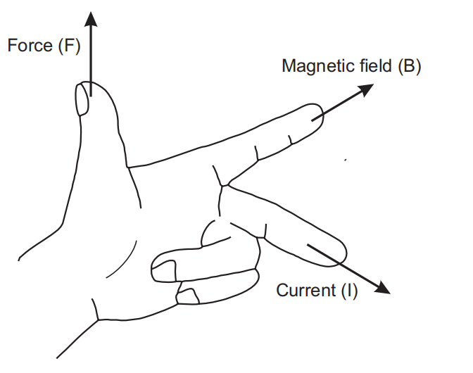
According to this rule, stretch (thumb, forefinger and middle finger of your left hand such that they are mutually perpendicular to each other.
If fore finger represents direction of magnetic field & middle finger represent direction of current, then thumb will point in the direction motion or force acting on the conductor.
Functioning of electric motor is based on this rule. It converts electrical energy into mechanical energy.
16. Michael Faraday– Gave the law of Electromagnetic Induction
17. Galvanometer: It is an instrument that can detect the presence of a current in a circuit. If pointer is at zero (the centre of scale) there will be no flow of current.
If the pointer deflects on either side right or left, this will show the direction of current. Represented by
18. Electro Magnetic Induction – Can be explained by two experiments
In this experiment, when the north pole of bar magnet is brought closes to the coil or away from the coil, we see momentary deflection in the needle of galvanometer on either side of null point. First right and then left.
Similarly, if we keep the magnet stationery and coil is made to move towards or away from the north pole of magnet. Again, we will observe deflection in the needle of galvanometer.
If both bar magnet and coil kept stationary, there will be no deflection in galvanometer
This experiment can also be done with the south pole of magnet, we will observe the deflection in galvanometer, but it would be in opposite direction to the previous case.
It concludes that motion of magnet with respect to coil or vice-versa, changes the magnetic field. Due to this change in magnetic field lines, potential difference is induced in the same coil, which set up an induced current in the circuit.
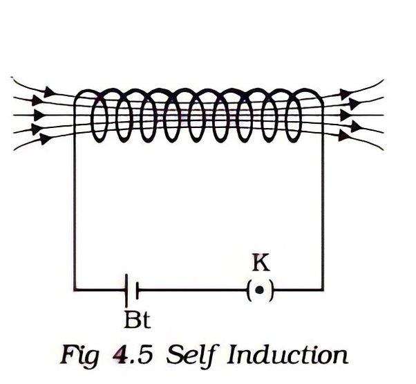
In this experiment plug in the key that is connect coil with battery and observe the deflection in galvanometer. Now plug out the key that is disconnect the coil-1 from battery and observe the deflection in galvanometer, which will be in reverse direction
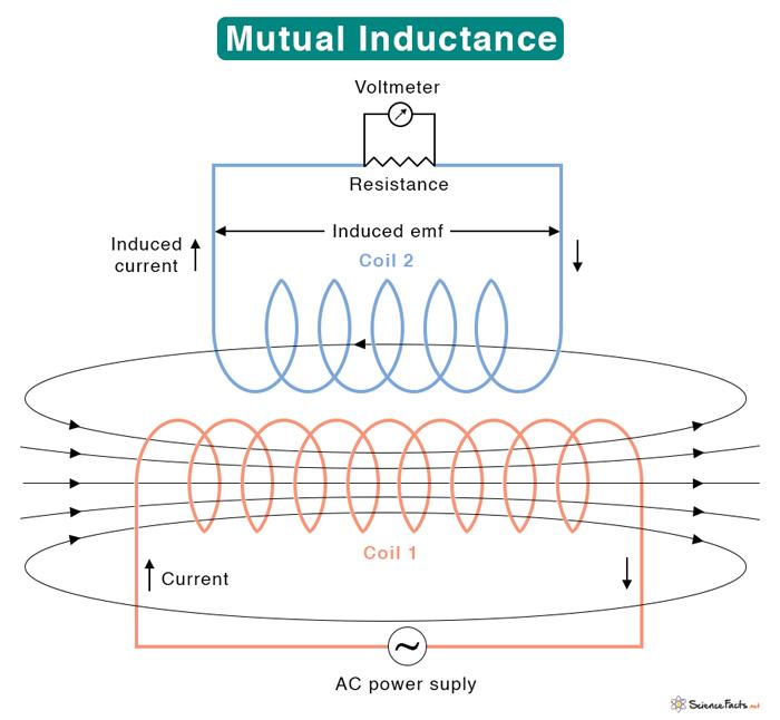
Hence, we conclude that potential difference is induced in secondary coil (coil-2), whenever there is a change in current, in primary coil (coil-1) (by on and off key).
This is because, whenever there is change in current in primary coil
Magnetic field associated with it also changes
Now, magnetic field lines around the secondary coil (coil-2) will change and induces the electric current in it (observed by the deflection of needle of Galvanometer in secondary circuit)
This process, by which changing of strength of current in primary coil, induces a current in secondary coil is called Electromagnetic Induction”
The induced current is found to be highest when the direction of motion of coil is at right angles to the magnetic field.
19. Fleming’s Right – Hand Rule
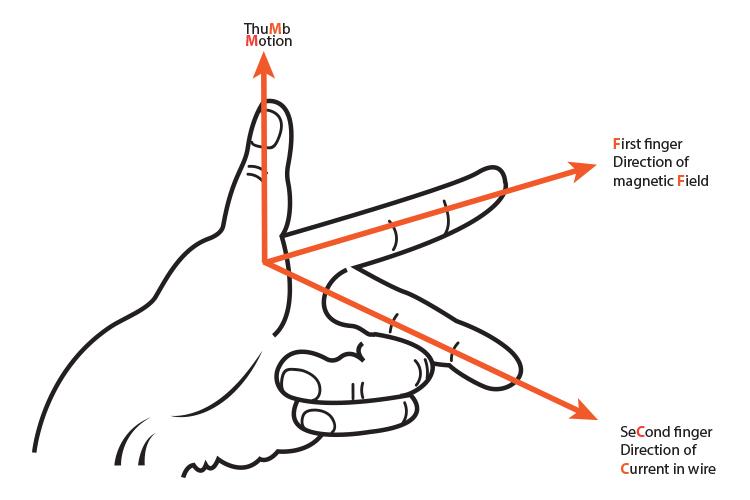
Three of them perpendicular to each other. Rule can be defined at
Stretch thumb, forefinger and middle finger of right
hand, so that they are perpendicular to each other. The forefinger indicates direction of magnetic field, thumb shows the direction of motion of conductor, then the middle finger will show the direction of induced current.
Electrical generator is based on the principle of electromagnetic induction. It converts mechanical energy into electrical energy.
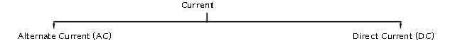

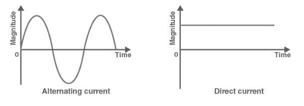
Advantages of Alternate Current (AC) over Direct Current (DC)
Electric power can be transmitted to longer distances without much loss of energy. Therefore, cost of transmission is low. In India the frequency of AC is 50Hz. It means after every 1/100 second it changes its direction.
22. Domestic Electric Circuits: –
In our homes, the electric power supplied is of potential difference V = 220V and frequency 50Hz. It consist of three wires: –
(1) Wire with red insulation cover – LIVE WIRE (POSITIVE) Live wire is at high potential of 220V
(2) Wire with black insulation cover – NEUTRAL WIRE (NEGATIVE) Neutral wire is at zero potential Therefore, the potential difference between the two is 220V.
(3) Wire with Green insulation cover- EARTH WIRE it is connected to a copper plate deep in the earth near house.
The metallic body of the appliances is connected with the earth wire as a safety measure.
Function-
Earth wire provide a low resistance to the current hence any leakage of current to the metallic body of the appliances, keep its potential equal to that of earth. That means zero potential and the user is saved from severe electric shock
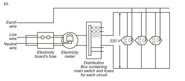
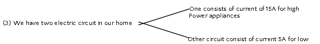
Point to be noted in domestic circuit
- Each appliance has a separate switch of ON/OFF
- In order to provide equal potential difference to each appliance, they should be connected parallel to each other. So that they can be operated at any time.
24. Short Circuiting-
Due to fault in the appliances or damage in the insulation of two wires, the circuit will offer zero or negligible resistance to the flow of current. Due to low resistance, large amount of current will flow.
According to Joule’s law of heating effect (H is proportional to P)
produced in live wire and produces spark, damaging the device and wiring.
25. Overloading-
Overloading can be caused by
(1) Connecting too many appliances to a single socket or
(2) accidental rise in supply voltage if the total current drawn by the appliances at a particular time exceeds the bearing capacity of that wire, it will get heated up. This is known as overloading.
Fuse a safety device can prevent the circuit from overloading and short circuiting