Think life without “electricity” in this modern society. Is it possible to survive without electrical energy in world of technology. Since we are science student, so it is necessary to understand the basic concept behind the word “electricity”
Charge ——–>(q)
It is a very small particles present in an atom it can be either negative (electron) or positive (proton)
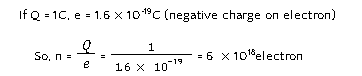
“Coulomb” is the SI unit of charge, represented by C.
Net charge (Q) – Total charge
ICNet charge is equivalent to the charge contained in nearly electrons

Join Offline Classes at OSF Education.
Read More Class 10 Solutions here.
Current
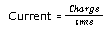
Rate of flow of net charge is called current. Denoted by (I)
I=Q/t
Where t is time
SI unit of current is “Ampere” rep.by A.
Ampere
Define as one coulomb of charge following per second
1A= 1coulomb/1sec
In an electric circuit the electric current flow in the opposite direction of the flow of electron (-ve charge) conventionally. It flows from the +ve terminal of battery or cell to -ve terminal.
Small quantity of current are expressed in
mA (milli Ampere) = 10-3 A
uA (micro Ampere) = 10-6 A
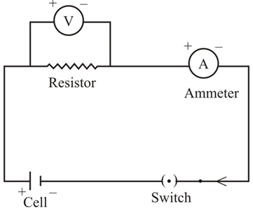
Ammeter- It is an instrument used to measure the electric current in a circuit. It is always connected in series ma circuit
It is represented by the symbol———— +A– —————— in an electric circuit. It has low resistance.
Electric Circuit- It is a closed path along which an electric current flow
The electron can only flow when there is difference of electric pressure.
For example “water flowing through a tube” It is only possible when there high pressure at one side and low at another side, then it will move from high pressure to low pressure..
In case of electric current, the flow charge is made possible due to chemical action with in a cell that generates the potential difference across the terminals of the cell.
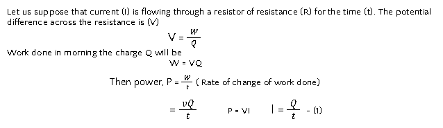
Electric potential Difference – It is defined as the work done in carrying a unit charge from one point to another between the two points of an electric circuits.
V=W/Q
where V – Potential Difference
W – Work
Q – Net Charge
SI unit of potential difference – Volts rep.by “V”
One Volt – when 1 Joule of work is done to carry one coulomb (10) of charge from one point to another of a current carrying conductor then the potential difference is sent to be IV.
VI=W/t
Voltmeter – It is an instrument, used to measure the potential difference and represented by the symbol
————– +V– ————- in an electric circuit. It is always connected in parallel across the points between which the potential difference is to be measured. It has high resistance.
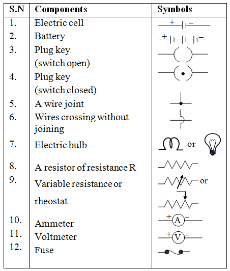
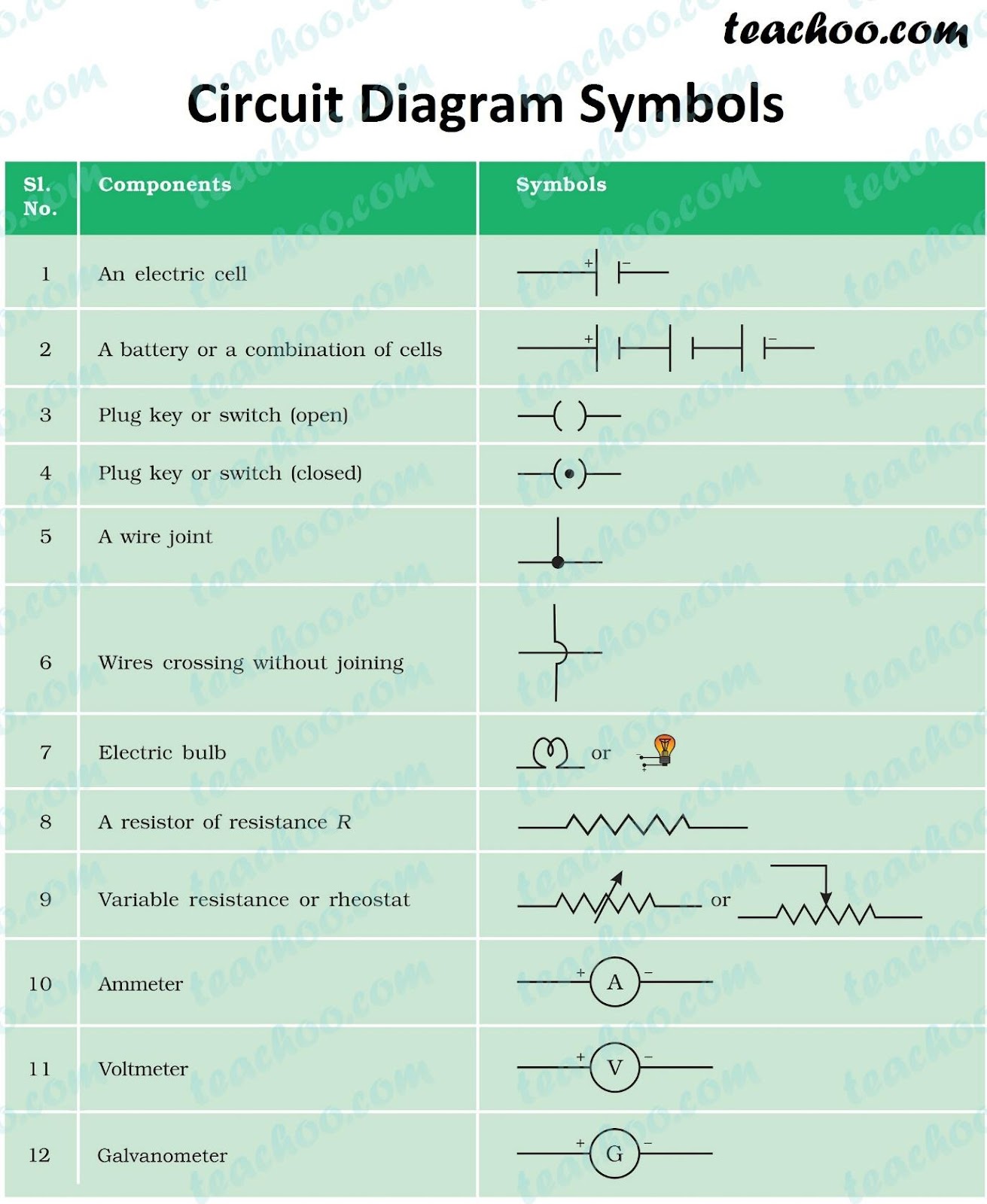
Symbols for some commonly used instrument in circuit diagrams
Georg Simon Ohm (physicist) 1787-1854
Found the relationship between the current (1) flowing through a conductor and potential difference (V) across the terminals of a conductor using the circuit diagram.
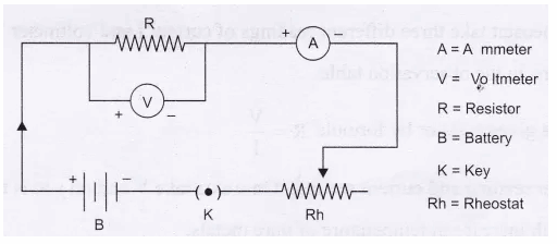
In this circuit diagram we come across two new symbols
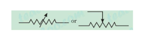
RHEOSTAT (Variable Resistance)
Ohm’s Law – he stated that the electric current flowing through a conductor is directly proportion at to the potential difference across its ends, provided the temperature remain constant (V is proportional to I)
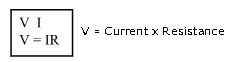
Where “R” is the proportionality constant for the given metal at given temperature and is said to be resistance, the graph between V and I is always straight line.
Resistance- It is the property of a conductor that opposes the flow of current. It is represented by ‘R’and symbol is
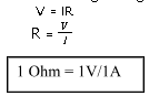
SI unit of resistance “Ohm” OR Ω
1 Ohm –The resistance of a conductor is said to be one Ohm, when the potential difference across the conductor is 1V and the current flowing through it is 1A.
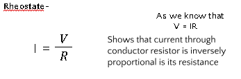
So to increase or decrease the current accordingly in the circuit a component is used is called “Rheostat”, that regulates the current without changing potential difference. Represented by “Rh

It a conductor has less Resistance, then more current will flow through it.
FACTORS ON WHICH RESISTANCE OF A CONDUCTOR DEPENDS-
- On its length (l)
- On its cross-sectional area (A)
- On the nature of material
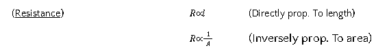

Where “” (rho) is a proportionality constant known as resistivity of the material of conductor.
Resistivity –
The resistance offered by a wire of unit length and unit cross – sectional area is called resistivity.
S.I Unit is Ωm
For a material irrespective of length and area. The resistivity is a constant.
Resistivity of a material vary with temperature
Resistivity of an alloy (homogeneous mixture of metals) is generally higher than of its constituent metals. Example Constantan (alloy of Cu & Ni)
Alloys have high resistivity and do not oxidize (burn) readily at high temperature, for this reason they are commonly used in electrical heating devices, like electric iron, heater, toasters etc. For example, “Tungsten” as filament of electric bulb.
Resistance in Series- (Maximum Effective Resistance)
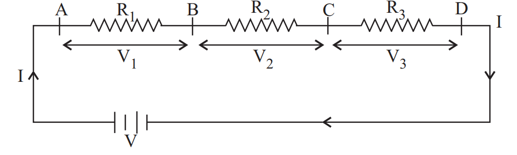
Let us take three resistance R1, R2 and R3 that are connected in series in a circuit.
The current (1) flowing through the resistance in series will remain same, where as the potential difference (V) across each resistor will be different
V = IR
V1 = IR1, V2 = IR2, V3 = IR3
Total potential difference (V) = V1 + V2 + V3 V = IR1 + IR2 + IR3 Putting the value of V, V1, V2 & V3
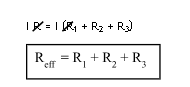
Thus, we conclude that effective Resistance of the several resistors joined in series is equal to the sum of their individual resistance
Resistance in Parallel (Minimum Effective Resistance)
Let us take three R1, R2 and R3, that are connected in parallel in the electric circuit.
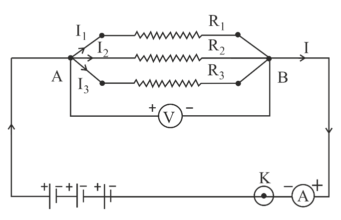
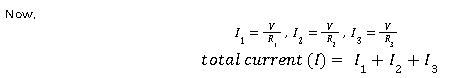
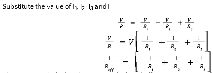
Thus, we conclude that the reciprocal of total effective resistance of the several resistors connected in parallel is equal to the sum of the reciprocals of the individual resistance.
Disadvantage of series connection in on electric circuit: –
- In series connection if any of the component fail to work, the circuit will break and then none of the component (ex. TV, bulb, fan.) will work.
- It is not possible to connect a bulb and a heater in series, because they need different value of current to operate properly.
Hence, to overcome this problem we generally use parallel circuit.
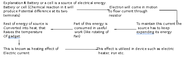
Heating effect of Electric Current:
Mathematical Expression:-
Heat energy supplied by the source for time t will be
H = P × t
Put equation (1) in equation (2)
H = VIt
= (IR) It [ V = IR Ohm’s Law]
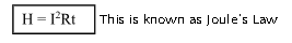
The low stated that the heat produced in a resistor is
- directly proportional to square of the current(I)
- directly proportional to resistance (R) for given current
- directly proportional to time() for which current flow through resistor.
Application of Heating Effect of Electric Current
(1) Used in electric iron, toaster, oven, heater etc.
(2) It is also used in bulb to produce light (Filament of bulb is made of strong metal with high melting point such as tungsten (m.pt-3380°C). This filament can retain as much of the heat generated as possible, to become very hot and emit light)
(3) It is also used in the “used connected in an electric circuit (Fuse a safety device, protect the circuits and appliance by stopping the flow of high current. The wire of fuse is made of an alloy of metals for e.g. Aluminum, Copper, Iron lead etc. The alloy should be of low m.pt and high resistivity, fuse is always connected in series circuit. When large current flow through the circuit, the temperature of fuse wire will increase. This melts the fuse wire and break the circuit
“Fuses” used for domestic purposes are rated as 1A, 2A, 3A, 5A, 10A etc. for various operation depending upon the power of appliance using
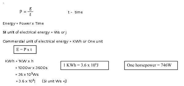
Example : let us consider an appliance “electric Iron” which consume 1KW electric power, at 220V
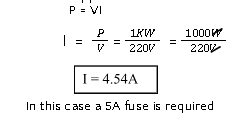
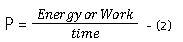
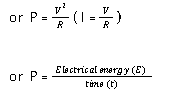
Electric Power: – In case of electricity, it is defined as the rate of change electrical energy dissipated or consumed in an electric electrical energy dissipated or consumed in an electric circuit.
P = VI power = Volt x Current
or P = I2R (V = IR Ohm’s Law)
SI unit of electric power is “Watt” (W).
1 Watt-Defined as the power consumed by a device, when 1A of current passes through it at the potential difference of 1V.
P = Volt x current (V x I) 1watt = 1 volt x 1 Ampere